CBI: CrOS Board Info
Terms
When we talk about CBI, we use the following definitions:
- Device: A computer running ChromeOS.
- Family: A set of devices which share the same reference design. (e.g. Fizz).
- Model: Within a family, devices are distinguished by non-customizable hardware features (e.g. chassis, motherboard). They’re grouped as a model and usually given a code name (e.g. Teemo, Sion). Within a model, devices are distinguished by SKU.
- SKU: Numeric value used to differentiate builds within same Model/Family. The SKU will change based on the build configuration of non-probable HW features (e.g. which daughter board is connected, convertible/clamshell, which audio codec HW is populated, etc.)
- Project: Avoided in this doc for its (too) wide usage.
Background
It’s desired to make a single firmware image support different board versions and variants to simplify development and manufacturing. To do so, firmware needs to identify the hardware, first. ChromeOS devices historically encoded such information in resistor straps. Today we store such information in EEPROM and call it CrOS board info (a.k.a. CBI). This page describes CBI data format, implementation, advantages, and caveats.
One of the obvious advantages is that EEPROMs can store more data using fewer pins. As the EC is connected to more chips, its I/O pins are becoming more precious. I2C buses exist nearly in all boards. Thus, adding an I2C EEPROM virtually consumes no extra pins.
Second, resistor strapping is significantly harder to be altered. Though this provides protection against accidental loss of information, hardware information becomes too rigid. EEPROM contents can be altered if proper tools and instructions are provided. It allows vendors and RMA centers to stock generic boards and convert them to a specific model as demands are revealed. This flexibility is one of the biggest advantages of the CBI/EEPROM solution over resistor strapping.
Since EEPROMs are physically separated from other data storage, if we choose, they can be locked down. ChromeOS already has this ‘write-protect’ feature built in the design. Data stored in write-protected storage can be changed only through authorized access. We can simply hook an EEPROM’s WP pin to this wire to get the access control aligned to other firmware storage and provide the same level of tamper resistance.
CBI Image Format
| Offset | # bytes | data name | description |
|---|---|---|---|
| 0 | 3 | MAGIC | 0x43, 0x42, 0x49 (‘CBI’) |
| 3 | 1 | CRC | 8-bit CRC of everything after CRC through ITEM_n |
| 4 | 1 | FORMAT_VER_MINOR | The data format version. It’s 0.0 (0x00, 0x00) for the initial version. |
| 5 | 1 | FORMAT_VER_MAJOR | |
| 6 | 2 | TOTAL_SIZE | Total number of bytes in the entire data. |
| 8 | x | ITEM_0,..ITEM_n | List of data items. The format is explained below. |
MAGIC
It’s fixed and invariable across format versions. This allows ECs and tools to quickly identify CBI data before parsing it.
CRC
8-bit CRC of data[4] through data[TOTAL_SIZE]. Invariable across format versions. It allows ECs and tools to detect data corruption.
FORMAT_VERSION
Stores the data format version. Starts with 0.0 (0x00, 0x00). ECs and tools are expected to be able to parse all the future versions as long as the major version is equal to or smaller than the parser’s version. Stored in little endian (1st half: minor version. 2nd half: major version) so that it can be interpreted as a single 16-bit value on little endian machines (x86 & ARM).
TOTAL_SIZE
The number of bytes in the entire data structure. This field helps older parsers compute proper CRC without knowledge on the new data items. The max is 0xFFFF.
Data Fields
Following after the header fields are data items. They are stored in an array where each element uses the following format:
| Offset | # bytes | data name | description |
|---|---|---|---|
| 0 | 1 | <tag> | A numeric value uniquely assigned to each item. |
| 1 | 1 | <size> | Total size of the item (i.e. <tag><size><data>) |
| 2 | x | <value> | Value can be a string, raw data, or an integer. |
Integer values are stored in the little endian format. They are written using the smallest size to fit the value and on read, padded with as many zeros as the reader expects.
Here are a list of standard data items. See ec/include/cros_board_info.h for
the latest information. Data sizes can vary project to project. Optional items
are not listed but can be added as needed by the project.
| Name | tag | type | sticky | required | description |
|---|---|---|---|---|---|
| BOARD_VERSION | 0 | integer | yes | yes | Board version (0, 1, 2, ...) |
| OEM_ID | 1 | integer | yes | no | OEM ID |
| SKU_ID | 2 | integer | no | yes | ID assigned to each SKU. |
| DRAM_PART_NUM | 3 | string | no | no | DRAM part name in ascii characters |
| OEM_NAME | 4 | string | yes | no | OEM name in ascii characters |
| FW_CONFIG | 6 | integer | no | yes | Bit-field that encodes information that the firmware needs to make decisions on |
| PCB_SUPPLIER | 7 | integer | yes | no | ID assigned to each PCB manufacturer (per-board) |
| SSFC | 8 | integer | no | no | Bit-field that encodes information that the firmware needs to make decisions on for probeable second source components |
| REWORK_ID | 9 | integer | no | no | Bit-field that encodes the reworks applied to the device |
| FACTORY_CALIBRATION_DATA | 10 | integer | no | no | Bit-field that encodes factory calibration data |
| COMMON_CONTROL | 11 | integer | no | no | Bit-field that encodes common control flags |
| BATTERY_CONFIG | 12 | binary | no | no | Battery configuration #0 |
| ... | ... | binary | no | no | Battery configuration #1 ~ 14 |
| BATTERY_CONFIG_15 | 27 | binary | no | no | Battery configuration #15 |
Sticky fields are those which are set before SMT and preflashed to EEPROMs. They're not expected to be changed after boards are manufactured. Non-sticky fields can be changed for example at RMA center if write protect is disabled.
Required fields are expected to exist on all devices.
BOARD_VERSION
The number assigned to each hardware version. This field ideally should be synchronously incremented as the project progresses and should not differ among models.
Assignment can be different from project to project but it’s recommended to be a single-byte field (instead of two-byte field where the upper half describes phases (EVT, DVT, PVT) and the lower half describes numeric versions in each phase).
OEM_ID
A number assigned to each OEM. Software shared by multiple OEMs can use this field to select a customization common to a particular OEM. For example, it can be used to control LEDs, which tend to follow an OEM's preference.
SKU_ID
The number used to describe hardware configuration or hardware features. Assignment varies family to family and usually is shared among all models in the same family.
In the past, some families use it as an index for a SKU table where hardware features are described for SKUs, or it has also been a bitmap where each bit or set of bits represents one hardware feature. For example, it can contain information such as CPU type, form factor, touch panel, camera, keyboard backlight, etc. Top 8 bits can be reserved for OEM specific features to allow OEMs to customize devices independently.
Now, the SKU_ID is not used by the firmware to make any decisions. The firmware code will use the FW_CONFIG field to make any branching decisions. This allows us to decouple the hardware identity (SKU_ID) from how the firmware needs to react (FW_CONFIG). A particular SKU_ID value implies one and only one value for FW_CONFIG. When HW identity is decoupled from firmware behavior, we can add new permutations of hardware (and thus new SKU values) without affecting the firmware code if the firmware code can treat the hardware the same (meaning two different SKU_IDs could have the same value for FW_CONFIG).
DRAM_PART_NUM (go/octopus-dram-part-number-retrieval)
A string value that is used to identify a DRAM. This is different from RAM ID, which is an index to a table where RAM configuration parameters are stored. RAM ID is encoded in resistor strapping. This makes RAM ID visually validatable (as opposed to being a field in CBI). DRAM_PART_NUM is used to track the inventory.
OEM_NAME (TBD)
OEM name in ascii string.
FW_CONFIG
A bit field that tracks the different permutations of HW that the firmware needs to be able to handle. The FW_CONFIG only contains the information that the firmware strictly needs to make a branching decision. For information about second source components, you may put them in SSFC instead if the component is probeable to avoid SKU explosion.
Any other information about a device should be captured and stored in the higher level configuration system. See SKU and FW Configuration Fields for more details.
Below are a few, non-exhaustive examples of how the firmware configuration bits could be portioned.
| Bits | Features | Use |
|---|---|---|
| 1 | Enabled sensors in EC (1b : yes) | EC enables sensor monitoring based on this bit. This should be set to 1b when the sensors are stuffed on a design (e.g. convertible) and 0b when the sensors are not stuffed (e.g. clamshell) |
| 1 | Has internal keypad (1b: yes) | Update keyscan_config based on presence of keypad on internal keyboard |
| 1 | Has AR camera (1b: yes) | Enables interrupts and updates drivers for AR based camera. |
| 3 | GPIO customization for SoC | 8 unique GPIO configurations. Values are assigned on a per-firmware build basis. |
| 2 | SARs customization for SoC | 4 unique SARs customization files. Values are assigned on a per-firmware build basis |
| 2 | VBT customization for SoC | 4 unique VBT customization files. Values are assigned on a per-firmware build basis |
| 1 | Touchscreen enabled for SoC (1b: yes) | AP enables bus and configures GPIOs for touchscreen device |
PCB_SUPPLIER
This field identifies the printed-circuit-board manufacturer for a device. The ID assignment is specific to a board.
SSFC
SSFC (Second Source Factory Cache) is a bit field that tracks the different permutations of second source hardware components that the firmware needs to be able to handle. Similar to the FW_CONFIG, the SSFC only contains the information that the firmware strictly needs to make a branching decision. All components in SSFC should be probable (e.g.: I2C, SPI or Strappings). If components are non-probable then they should be encoded into FW_CONFIG instead of SSFC.
The difference between SSFC and FW_CONFIG is that FW_CONFIG is bound to SKU, but SSFC is independent of SKU. Devices with the same SKU must have the same FW_CONFIG value, but can have different SSFC values. Putting configs into SSFC prevents SKU explosion when a device has many second source components.
REWORK_ID
A 64-bit field that tracks the modifications applied to the device. What rework each bit represents can be independently defined by each project.
FACTORY_CALIBRATION_DATA
A 32-bit field that encloses the data from factory calibration such as LED or other components.
This field should only be used for calibration data required by the EC. Calibration data required by the OS should be placed in VPD instead.
COMMON_CONTROL
A 32-bit field that encodes common control flags. This should be used to alter behavior of a common feature which is not unique to a particular board or board family.
BATTERY_CONFIG ~ BATTERY_CONFIG_15
A binary field that encodes battery configuration data. Multiple slots are available to support battery swap.
Hardware
Firmware Write Protection
ChromeOS devices have the global write protect line, WP_L, which is
controlled by Cr50 and a servo, and used to protect various firmware images (AP,
EC, FPMCU, etc.). The WP pin of an EEPROM should be connected to WP_L. CBI data
will be protected as securely as other RO firmware images and can be changed at
RMA center or by developers for special needs.
While AP SPI flash and EC SPI flash also combine the internal status registers to determine the WP state, WP of CBI EEPROMs will be controlled by the WP signal only. When write protect is enabled, the EEPROM must protect entirely or partially the region where CBI data is stored.
We'll make a change with Cr50 such that when AP SPI WP is deasserted, Cr50
accepts a special host command which disables WP_L (only until the next
reboot). This allows CBI to be modified in the factory before the board is
finalized, that is, before the AP SPI WP is enabled.
I2C bus
It is recommended to select an I2C bus, which is quiet during power on after reset. An I2C device can wedge a bus. CrOS EC is capable of unwedging a bus but it doesn't always work.
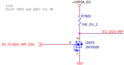
Circuitry
WP should be connected to the same wire as the write-protect pin of the EC SPI flash.
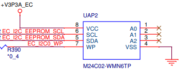
The power well should be the same as the EC. When the WP is high, the data is write protected. If the WP pin of an EC SPI Flash has active low logic (low = protect), a MOSFET can be used to reverse the voltage:
The following EEPROM parts have been tested and deployed on the past projects:
- M24C02-WMN6TP
- M34E02-FMC6TG
They are pin-to-pin compatible. M34E02 has a capability to protect only the top half but this feature is not currently used.
Testing
You can evaluate implementation as follows:
- Boot the device multiple times. Verify the data is consistently printed every time.
- Try cbi command on EC console multiple times. It reads the whole EEPROM data and dumps it. If I2C bus has a low quality signal, you may observe failed reads.
- Try enable and disable hardware write protection. Verify
ectool cbi setcommand fails or succeeds as expected. - Verify default values and errors are handled. If CBI is for some reason broken, the software stack should choose the default values which have the least impact on the system stability.
Software
EC firmware
CBI should be read up to two times (back-to-back) per boot per image. That is, on normal boot, EC RO should read it and EC RW should read it once. Once reads are attempted, the result is preserved even if both reads fail. This would prevent the system from running in an inconsistent state. b/80236608 explains why we don't let the EC keep reading CBI.
The earliest timing CBI can be read is at HOOK_INIT with HOOK_PRIO_POST_I2C.
cbi-util
A tool which runs on a build machine. It creates a EEPROM image file with given field values. Manufacturers use CBI image files to pre-flash EEPROMs in large volume. This tool also can print the contents of a CBI image file.
ectool
A tool which runs on a host (i.e. Chromebooks). It can fetch CBI data from the EEPROM (through the EC). Manufacturers can use this tool to validate the EEPROM contents. If the board is not write protected, ectool can change the CBI. Note that some fields are not expected to be changed after the board is manufactured. The data of existing fields can be changed and resized.
mosys
Mosys is a tool which runs on the host to provide various information of the host. One of its sub-command, platform, retrieves board information (e.g. SKU, OEM) from SMBIOS, which is populated by coreboot. We’ll update coreboot so that it’ll fetch board information from EEPROM (via EC) instead of resistor strapping.
cbi_info
This is a script used by debugd to include CBI dump in user feedback reports. Currently, it prints only BOARD_VERSION, OEM_ID, and SKU_ID.
Limitation
It requires the EC to initialize an I2C controller and its driver. There may be rare cases where board info is needed before these are initialized. To handle such cases, we may need to add simplified I2C API. Simplified I2C API would have the following features:
- Does not do write
- May only read a single byte at a time
- May run at lower frequency
- May assume no multitasking (thus implement no concurrency control)
- Exist only in RO copy